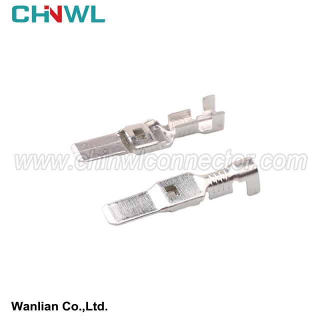

CHINWL #: DJ621Y-6.3B
Mfr. #: 0-1544218-1 1544218-1
|
Wanlian part number: |
|
DJ621Y-6.3B |
|
Original number: |
|
0-1544218-1 1544218-1 |
|
Gender: |
|
Female |
|
Specification: |
|
Copper Alloy, Brass, Phosphor Bronze, Nickel. |
|
Type: |
|
Terminal |
|
TUV, TS16949, ISO14001, ISO 9001, RoHS conform: |
|
Yes |
|
MOQ: |
|
No minimum order quantity |
|
Supply sample: |
|
Yes |
|
Customized drawing with Decal, Frosted, Print are available as request |
|
Yes |
|
Payment method: |
|
We accept Paypal, TT, Alipay, West Union etc. |
|
Transportation method: |
|
Air Transport: UPS, DHL, FEDEX etc; Sea Transport; Railway Transport; Freight Forwarding etc. |
|
Production Capacity: |
|
1000000pieces/Month |

1.1 U -type connection end is cold and stamped
The U -type connection end is referred to as the U -type pressure connection, which is a traditional wire connection pressure method. The U -type pressure connection is based on the connection line diameter and the U -shaped terminal (Figure 1) and the pressure connection machine, and formulate a dedicated pressure connection mold and clamp for the U -shaped terminal of each model, and then two or two or more. The wires of the U -shaped terminal are pressed together with the help of the U -shaped terminal pressure. U -shaped voltage seizure diagram is shown in Figure 2. See Table 1 in the selection of U -shaped terminals and crusher, and the intermodal pressure connection standard sample is shown in Table 2.
The pressure connection machine is equipped with a pressure monitoring device, as shown in Figure 3. When abnormalities (shallow, deep beating, leakage, interruption of copper wire, core wires, etc.), automatically alarm and lock the pressure connection equipment, you must manually remove the lock. The pressure connection parameters and detection basis shall meet the requirements of QC / T29106. The closed height is continuously adjusted, the accuracy can reach 0.03 mm, the transmission structure is simple, the operation is stable and reliable, and the working state will only work instantly in the pressure connection. Save power and unique overload protection functions. Nominal pressure 80 kn, adjustment volume 2 mm (0.079 in), and 40 mm (1.575 in). The contact resistance is large. If the mechanical strength cannot be guaranteed, the welding operation is needed; the production efficiency is low, and the welding requires welding agents and solder; the welding process is polluted, the welding point resistance is large, and the phenomenon of virtual welding is prone to occur. Seeing Table 3 in several common states in U -shaped pressure. The U -shaped crushing qualified product is shown in Figure 4.
Human hearing can only hear the sound of vibration frequency in 20 Hz ~ 16 kHz, and the vibration beyond this range is called ultrasonic. The ultrasonic welding machine and welding area are shown in Figure 5. It is a high -frequency electrical energy of 20 kHz or 40 kHz through a transistor function device to convert it to the converter through a transforming electrical frequency of 50/60 Hz.
The converter converts electrical energy into the mechanical vibration energy for ultrasonic, and the pressure regulating device is responsible for transmitting the mechanical energy of the transformation to the welding head of the ultrasonic welding machine. The welding head is an acoustic device that can directly transmit the mechanical vibration to the need to compose the product. The vibration is passed to the bonding surface through the welding works parts, and the vibration friction produces thermal energy to melt the plastic. The vibration will stop when the melting state is reached by the interface. The short -term maintenance can make the molten bonding the strong molecular bond when the bonding surface is solidified. The cycle is usually completed in less than one second. Figure 6 is a schematic diagram of the composition of the welding area.
The tool head is mainly composed of four components: welding tank, anvil connection block, anvil top block, and polymerization module. During welding, the line is tightly arranged vertically, and the anvil is connected to the block. After the foot switch, the aggregation module moves towards the top block of the anvil. Pressing it in the welding area, the welding head is vibrated, and the energy is passed to the copper thread, so that the wire beam is welded together. During welding, except for the welding tin vibration, other tool heads are not moving. After the welding is completed, the polymerization module is returned, the top block of the anvil is returned (XL machine), and the Ivic connecting block rises, so that the wire beam can be removed. Because the welding head is vibration, and other tool heads are fixed, in order to prevent the welding machine from forming welding between the tool head and the welding head, the surface of the surface of the weld is Remain 0.025 mm on the side of the Ivic connecting block, so that the welding tank cannot be in contact with other tool heads. There are no debris such as copper between these gaps, otherwise the work surface of the tool head will be eroded during welding, and the circuit board can be damaged in severe cases. Because the ultrasonic vibration is generated by the welding head, its energy is passed to the top of the iron avic. Put the line at the bottom, close to the welding head surface, and the thin lines are arranged vertically upward in turn, so that the thick line can obtain large energy, thereby preventing insufficient welding or welding. Vertical arrangement can prevent side welding, thereby ensuring welding quality.
Simple instructions:
We have product Catalogue,please contact us on skype,WhatsApp or Email.
If you can't find a product on our website or catalog, We deal with over 10,000 items, our catalog doesn’t cover all products. And we are developing 100+ molds yearly, which means around 10 new products are created in our factory. So don’t go away, just send us your photo or part no, we’ll check for you.