
Wanlian #: 155-03800
Mfr. #: 155-03800
|
Wanlian part number: |
|
155-03800 |
|
Original number: |
|
155-03800 |
|
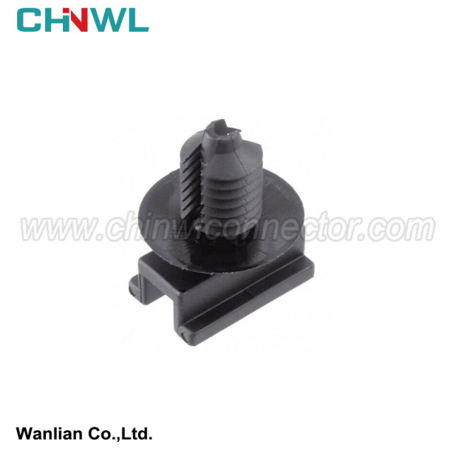
Color: |
|
Black |
|
Type: |
|
Clip |
|
TUV, TS16949, ISO14001, ISO 9001, RoHS conform: |
|
Yes |
|
MOQ: |
|
No minimum order quantity |
|
Supply sample: |
|
Yes |
|
Customized drawing with Decal, Frosted, Print are available as request |
|
Yes |
|
Payment method: |
|
We accept Paypal, TT, Alipay, West Union etc. |
|
Transportation method: |
|
Air Transport: UPS, DHL, FEDEX etc; Sea Transport; Railway Transport; Freight Forwarding etc. |
|
Production Capacity: |
|
1000000pieces/Month |

3 Performance -based circuit design method
The wire beam circuit is the core of the circuit connection. The safety and reliability of the circuit connection must be met. The wires and connectors in the circuit design must follow the requirements of the load and the environment. There is a detailed description. This article only illustrates how to ensure the design of the circuit performance from the choice of the path of the circuit.
First of all, the design of the circuit must avoid the invalid mode that cannot be detected, as shown in Figure 4, the rear part of the fuse of the fuse with the relay coil and the contact side of the contact side. This design is very common in the design of the vehicle circuit. When the relay coil end and the terminal terminals are different, this design is obviously reasonable, but when the relay coil end and the contact terminal terminal are the same, this design is currently in the case where the terminal is inserted into the relay hole. The electrical inspection equipment cannot identify such a failure method.
Therefore, this way of design is not available in some cases. Of course, the design environment and the manufacturing environment of different design engineers are different, and the specific failure mode will be different, but the avoidance mode in the circuit design must be considered first.
On the other hand, the current level of automotive electronicization has improved significantly. As an electronic carrier, the electromagnetic environment facing cars is more complicated, and how to reduce electromagnetic interference in wire beam circuit design is an inevitable topic. Coupling interference (Figure 5), power interference, iron interference, radiation interference, etc. will adversely affect the normal work of the electrical component, and the circuits in the wiring beam are tied together, between the circuit between the wire beam, between the cable beam and the metal conductor, and the metal conductor is generated. The wire coupling interference is particularly prominent on the online beam.
To reduce the coupling interference in the circuit design, we must first distinguish between interference circuits and sensitive circuits. To put it simply, perceptual load circuits such as ignition coils, speakers, motors, etc. belong to the interference circuit, and the circuit such as image, radar probe, low -power LED lights, and various sensors belong to the sensitive circuit. During the design process Need to be arranged separately. Tests show that increasing wire spacing can reduce high -frequency interference (Figure 6). When distinction is impossible, the function test is required to inject interference through the wire to determine the correct circuit design.
At the same time, in order to reduce the effects of wire beam radiation and coupling, the circuit circuit area and line beam length should be reduced as much as possible. In the car design of the car, you need to reduce the circuit area of the wire beam as much as possible, especially the power cord and the iron wire. It is required to take as much as possible in the middle line beam as possible. At the same time More than 50cm.
In addition to the layout of interference circuits and sensitive circuits, the twisted and shielding lines used on the beam on the beam also need to pay attention to the shielding expectations: the two wire diameter of the two wires of the twisted twisted twist wire The length should be the same, the twisted distance is best 10 ~ 20mm, the specific twisted distance is subject to the test test; the shielding layer and the iron terminal should be connected to the shielding shell at the beginning and at the end of the end. The signal line is completely shielded. For the component shell connected to the shielding cable is not a metal structure, the metal conductive card can be used to press the shielding layer on the metal plate that is reliable to connect to the body. The shielding performance should reach 60dB.
Simple instructions:
We have product Catalogue,please contact us on skype,WhatsApp or Email.
If you can't find a product on our website or catalog, We deal with over 10,000 items, our catalog doesn’t cover all products. And we are developing 100+ molds yearly, which means around 10 new products are created in our factory. So don’t go away, just send us your photo or part no, we’ll check for you.
grey