
Wanlian #:
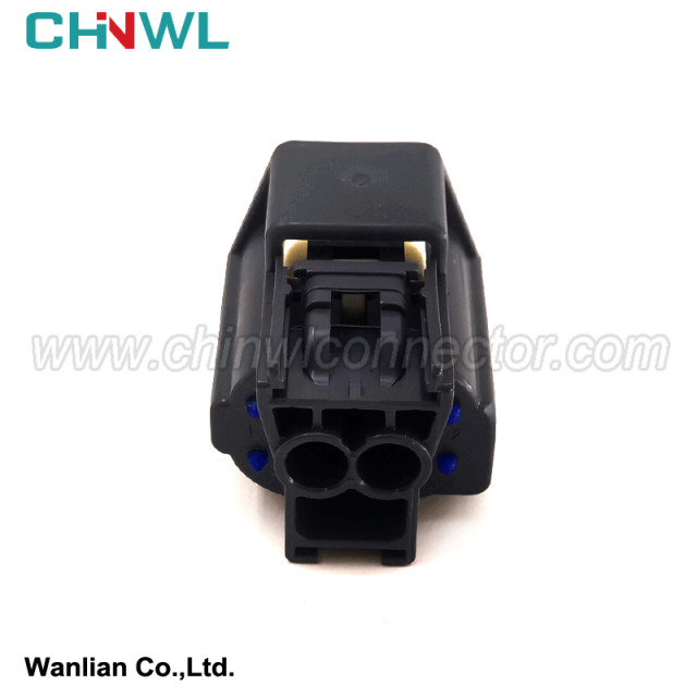
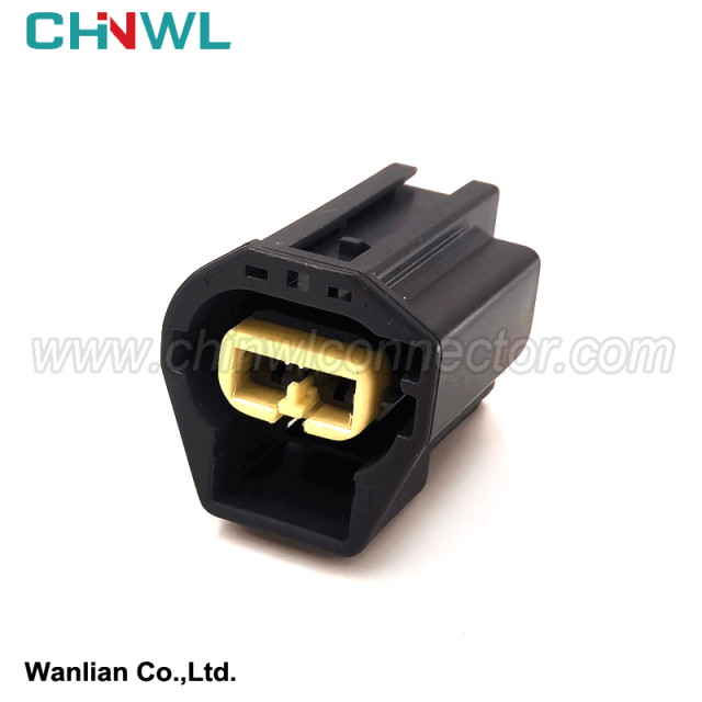
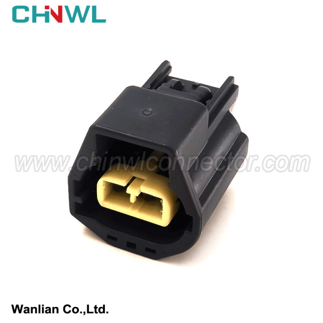
Mfr. #: 7183-5575-10
|
Wanlian part number: |
|
|
|
Original number: |
|
7183-5575-10 |
|
Gender: |
|
Female |
|
Specification: |
|
Housing: PBT+G; PA66+GF; PA66; PBT; Nylon |
|
Type: |
|
Connector |
|
TUV, TS16949, ISO14001, ISO 9001, RoHS conform: |
|
Yes |
|
MOQ: |
|
No minimum order quantity |
|
Supply sample: |
|
Yes |
|
Customized drawing with Decal, Frosted, Print are available as request |
|
Yes |
|
Payment method: |
|
We accept Paypal, TT, Alipay, West Union etc. |
|
Transportation method: |
|
Air Transport: UPS, DHL, FEDEX etc; Sea Transport; Railway Transport; Freight Forwarding etc. |
|
Production Capacity: |
|
1000000pieces/Month |

1.4.7 Signal system wiring law
The signal system is mainly composed of steering signal lights, hazard warning signal lights, brake signal lights, reversing signal lights, speaker sounds, etc. These signals are issued by the driver to other vehicles and pedestrians according to road traffic conditions, with strong randomness and generally controlled by themselves. If the brake signal is mostly controlled by the brake pedal; the reversing light is mostly controlled by the transmission rod pouring shaft, and it can be connected without the driver's special operation. The speaker button is mostly on the steering wheel. transmit signal.
The steering signal light has a certain flash frequency. The national standard specifies that 60 to 120 times/min, Japan stipulates that (85 ± 10) times/min, the power of the turning light is often 21-25W, the front and back, left and right, large vehicles and cars are often often vehicles and cars. There is a steering signal light on both sides. The general connection method of its circuit is: steering lights and steering light switches, and the normal shutdown contact switch of the risk warning light switch with the risk warning light switch of the shift light switch, that is, the steering signal light is used when the ignition switch is at work gear (on).
The use occasions of the hazard warning lights are: the car has a failure or danger that cannot be driven; the car has the task of tractioning a car and requires him to pay attention; the car needs to be prioritized, and he needs to avoid it. Therefore, the hazard warning light can be used when the engine is not working. At this time, there is no need to connect the ignition system and the instrument alarm light. To this end, there is a hazard warning switch. It is a multi -knife linkage switch, which is connected to the battery wiring while disconnecting the ignition switch wiring. Flash relay and bulb power supply directly comes from the battery, and connect the output of the flash relay with the left and right direction lights, that is, when the flash relay moves, the left and right direction lights and indicator lights emit dangerous signals at the same time.
1.4.8 Electronic control system wiring law
The wiring law of the electronic control system circuit can be summarized as: the ECU control circuit must accept ignition switch control, and various sensors must enter the working conditions at any time. For example, a magnetic pulse or Hall -style sensor can generate pulse voltage signals; some sensors are made of thermistor, the resistance value changes, and the output voltage also changes. Temperature sensor, etc. Electronic control system execution agencies are controlled by ECU and have self -diagnostic functions. There are two modes of ECU work: opening and closed -loop control. Fuel spraying control: After the engine ECU receives the input signal, it only responds according to the pre -set program, and the signal of the oxygen sensor will not be monitored. Open -loop operating conditions include warm machines, deceleration conditions, and full operating conditions of the throttle. Received control of fuel injection: The engine ECU detects the signal of the oxygen sensor, so that the ECU controls the fuel injection pulse width to get the ideal air -fuel ratio, reaches the best fuel economy, and reduce emissions. The closed -loop operating conditions include idling conditions and cruise conditions.
When the electronic control system is wiring, pay attention:
① The circuit schematic diagram of the model to prepare for the wiring model. If there is no circuit diagram, it is best to draw a wiring sketch in the real body, which will bring great convenience to the wiring maintenance work;
② Because the maintenance requires a temporary external wiring, you must pay attention to the insulation to prevent short circuit;
③ Do not bring a power wiring. When the wire is damaged, the wire of the original rules model is replaced. The connection should be reliable to minimize the contact resistance at the connection;
④ After the wiring is completed, the original wiring requirements should be tied up.
Simple instructions:
We have product Catalogue,please contact us on skype,WhatsApp or Email.
If you can't find a product on our website or catalog, We deal with over 10,000 items, our catalog doesn’t cover all products. And we are developing 100+ molds yearly, which means around 10 new products are created in our factory. So don’t go away, just send us your photo or part no, we’ll check for you.