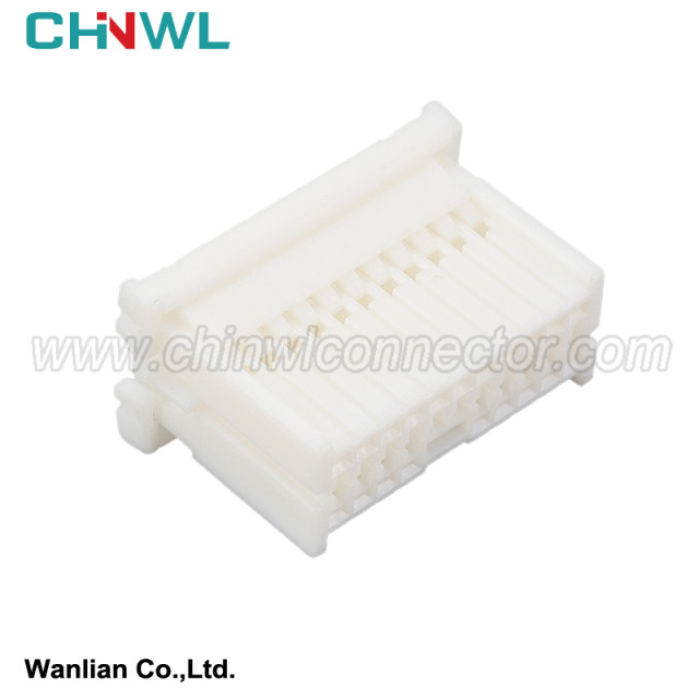
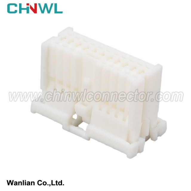
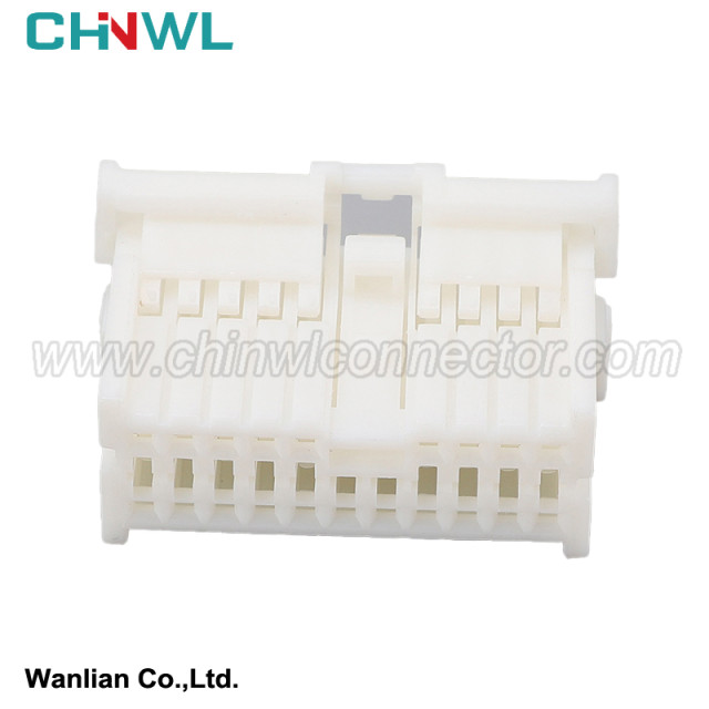

Wanlian #: WL206S2-1.2-21
Mfr. #: 936473-1 1123379-1 MG653026
|
Wanlian part number: |
|
WL206S2-1.2-21 |
|
Original number: |
|
936473-1 1123379-1 MG653026 |
|
Gender: |
|
Female |
|
Specification: |
|
Housing: PBT+G; PA66+GF; PA66; PBT; Nylon |
|
Type: |
|
Connector |
|
TUV, TS16949, ISO14001, ISO 9001, RoHS conform: |
|
Yes |
|
MOQ: |
|
No minimum order quantity |
|
Supply sample: |
|
Yes |
|
Customized drawing with Decal, Frosted, Print are available as request |
|
Yes |
|
Payment method: |
|
We accept Paypal, TT, Alipay, West Union etc. |
|
Transportation method: |
|
Air Transport: UPS, DHL, FEDEX etc; Sea Transport; Railway Transport; Freight Forwarding etc. |
|
Production Capacity: |
|
1000000pieces/Month |

2.6.1 ignition switch
The ignition switch is the most important switch in the automotive circuit, which is mainly used to control the ignition circuit. In addition, it also controls the magnetic field circuit, instrument and lighting circuit of the generator, the launch of the relay circuit and auxiliary electrical appliances. The commonly used ignition switch has a three -gear formula and four -shield formula.
(1) The three -speed ignition switch three -speed ignition switch has 0, Ⅰ, Ⅱ (or lock, on, start) gear. When 0, the key can be inserted or unplugged freely, rotating 40 ° clockwise to Ⅰ transmission, and continuing to rotate 40 ° to Ⅱ gear. After the external force is eliminated, it can automatically reset to the I. shows the three-speed ignition switch of Jetta Motor.
Three-speed ignition switch wiring diagram
The ignition switch is located in the 0 position: The ignition switch is in a closed state, the car's steering wheel is locked and has anti -theft function. At this time, the power bus 30 is connected with the P end of the P end. Operating the parking light switch can light up the parking lights, whether the ignition switch is or the ignition switch is the ignition switch. It has nothing to do with it. If the ignition switch key is inserted, it will be connected to 30 with the SU -side and the beeurger can work.
The ignition switch is located at the Ⅰ position: After starting, release the ignition switch key, and the ignition switch will automatically rotate back to the position Ⅰ counterclockwise. This is the work gear. At this time The ignition system continues to work, and the X -pass power allows the front lights and fog lights to meet the needs of night driving.
The ignition switch is located in the Ⅱ position: The power supply bus 30 and 50, 15, and SU terminals are connected to make motivation to operate, and 30 and 15 connect the ignition system. Due to P -end power off, the parking light cannot work; due to the X -end power cutting, the front lights, fog lights, etc. cannot work. In this way, the electric equipment with a large power consumption of front lights and fog lights is turned off to achieve the purpose of unloading, so as to meet the needs of a large current input motivation when starting. After the engine starts, the ignition switch should be released immediately to return it to the position Ⅰ, cut off the current of the motor, and the starter drives the gear to return.
(2) A large number of four -speed ignition switches are used in the four -speed ignition switch. There are four gears (or 0, Ⅰ, Ⅱ, III)in the four gear-ignition switch (or 0, Ⅰ, Ⅱ, Ⅲ). Work block, other unchanged.
Fig
The key after locking the car will be in a "lock" state. At this time, the key not only locks the turntable turntable shaft, but also cuts off the entire vehicle power.
The "ACC" state is the power supply connecting some electrical appliances, such as audio and car lights.
The key is in the "ON" state when normal driving, and all circuits of the entire car are in a working state.
The "START" or "ST" gear is the starting gear of the engine. After starting, the ignition switch is released, and the ignition switch will automatically return to the "ON" gear.
The following is the schematic diagram and circuit diagram of the Great Wall Haval four -speed ignition switch. The BT1 and BT2 terminals of the ignition switch are power supply input. , The engine ECU and the oil pump relay, the ST terminal is the start control, the K1 terminal is output to the central door lock controller, and the K2 is the ground terminal.
(3) The ignition switch with intelligent entry and starting systems With the development of automotive electronic technology, more and more vehicles use intelligent entry and startup systems. The ignition switch uses the ignition switch with intelligent entry and start -up system .
The ignition switch of intelligent entering and starting the system with intelligence
When the smart key is inside the car, press the "EngineStartStop" switch (one -click boot switch) to switch the switch mode, start the engine or turn off the engine.
In the parking state, do not step on the clutch pedal (manual transmission vehicle) or brake pedal (automatic transmission vehicle), and press the switch directly to switch the switch mode. Press each button to start the switch at a time, and the switch switches in the order shown in the order below.
Simple instructions:
We have product Catalogue,please contact us on skype,WhatsApp or Email.
If you can't find a product on our website or catalog, We deal with over 10,000 items, our catalog doesn’t cover all products. And we are developing 100+ molds yearly, which means around 10 new products are created in our factory. So don’t go away, just send us your photo or part no, we’ll check for you.