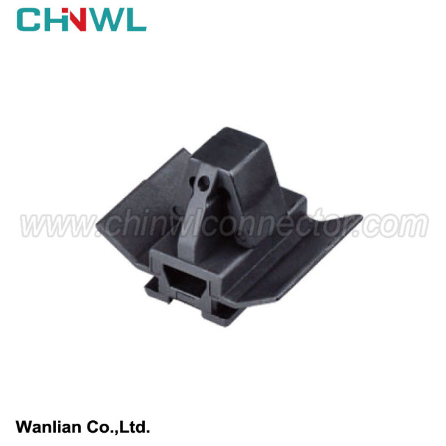

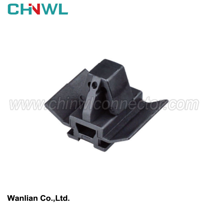
Wanlian #:
Mfr. #: ZF-003
|
Wanlian part number: |
|
|
|
Original number: |
|
ZF-003 |
|
Color: |
|
Black |
|
Type: |
|
Clip |
|
TUV, TS16949, ISO14001, ISO 9001, RoHS conform: |
|
Yes |
|
MOQ: |
|
No minimum order quantity |
|
Supply sample: |
|
Yes |
|
Customized drawing with Decal, Frosted, Print are available as request |
|
Yes |
|
Payment method: |
|
We accept Paypal, TT, Alipay, West Union etc. |
|
Transportation method: |
|
Air Transport: UPS, DHL, FEDEX etc; Sea Transport; Railway Transport; Freight Forwarding etc. |
|
Production Capacity: |
|
1000000pieces/Month |
2.10.5 What is NTC thermistor?
(1) NTC thermistor characteristics Non -metallic substances have thermistor. NTC represents "negative temperature coefficients", and its resistance value decreases with increased temperature . The resistor can be heated directly through the heating characteristics of the current, or indirectly heating through the exogenous.
3.1.1 Types of automobile circuit diagram
Automotive circuit diagram is a line symbol specified in national standards, and the structure composition, working principles, work processes and installation requirements of automotive electrical appliances are made, and it also includes a diagram and a simple structural schematic diagram.
In order to conveniently repair, inspect, install, and wiring car circuits. According to the different purposes of the car circuit diagram, it can be drawn into different forms of circuit diagrams. It mainly includes the schematic frame diagram, the wiring graph (installation chart), the part of the part, the wiring chart, the circuit schematic diagram, etc.
(1) Principle Fragments (System Charts) Because the electrical system of the car is more complicated, in order to generalize the basic composition and interrelationship of each car electrical system or sub -system, the schematic frame diagram is often used (Toyota car system is called the system diagram) Essence The so -called schematic frame diagram refers to a simple diagram that uses a box of symbols or comments, which means that the basic composition of automotive appliances, mutual relationships, and its main characteristics. The object described by the schematic box diagram is the main feature of the system or sub -system. It describes the content of the content. It is used to indicate the basic composition of the system or the system.
On the schematic box diagram, we can see the connection relationship of the entire system, which composition is composed of what components, which components have been connected to which electronic control units, and which components have been controlled, etc., etc., etc. However, the principle box diagram simply explains the connection relationship of the system and components, and cannot reflect the specific direction of the circuit .
Principles Fragics
(2) Wire beam diagram (installation diagram) As there are more and more electric equipment and electrical control units on the car, there are more and more connection wires that are needed. In order to install convenience and protect the wires at the same time, many wires on the same road are bandaged with cotton yarn or polythlotononhechide plastic bands into bundles.
The wire beam is a local circuit diagram drawn based on the actual installation site of the electrical equipment on the car.
In actual maintenance and detection, the wiring beam diagram can help detect technicians quickly determine the position of the inserter and connect the wire. The car circuit line beam diagram is often used in the connection, maintenance and wiring of the car factory's general loading line and repair shops.
The wiring beam diagram mainly shows that the connection site of the wire beam and the electrical appliances, the tags of the wiring terminal, the wire head, the connection (connector) of the connector (connecter). This kind of diagram generally does not depict the direction of the wire inside the beam in detail. Only the line head and plug in the online beam are numbered or marked with the letters.
The wiring beam diagram can be divided into engine wiring, instrument panel beam, bottom panel beam, body wiring, etc. according to the function of the wiring position and wiring beam.
Simple instructions:
We have product Catalogue,please contact us on skype,WhatsApp or Email.
If you can't find a product on our website or catalog, We deal with over 10,000 items, our catalog doesn’t cover all products. And we are developing 100+ molds yearly, which means around 10 new products are created in our factory. So don’t go away, just send us your photo or part no, we’ll check for you.
grey